Skydiver — scratch-built l1 Rocket
9:06 AM on Saturday, July 10th, 2021 (West Lafayette, IN)
Towards the latter half of last summer, I found an interest in rockets. Model rockets, to be exact, with never anything using more than a C class motor. For those who aren’t familiar with the lavish world of solid rocket motor classifications, they work like this: rocket motors are assigned a letter, such as A, B, or C, and so on. A C class motor has double the total impulse of a B class motor, and a D class motor has double the total impulse of a C, and so on and so forth until you reach the really big motors like O class motors. It thus makes sense, given solid rocket propellant does indeed combust, that there are certain levels that must be attained in order to use certain motor classes. For most states, the highest class you can buy with no certification is a G motor. To buy an H or I class motor, you need a Level 1 certification from either the Tripoli Rocketry Association or the National Association of Rocketry. This entails launching and successfully recovering a rocket that uses an H or I class motor. After that, you can go on and get your Level 2 certification by taking an exam and successfully launching and recovering a rocket with a J, K, or L impulse motor. After that, comes your Level 3 certification, which is a whole other can of worms and something I’ll be working on in the future. What this all essentially boils down to is a license to spend more money, which I was eager to do. Or rather spending money was a means to launch rockets, and I really wanted to launch more rockets.
Getting my L1 certification had been in the back of my mind for the latter half of my Spring 2021 semester, with many day dreams about my own big rocket that would go sky high, and of all the possibilities for the electronics I could stuff into it. Then I joined Purdue Space Program, and went to the Aerospace Sciences Laboratory at Purdue one weekend to help out on a build. I got there in the morning excited, and left there that night knowing I just had to do it now. Working on the club’s rocket had been so much fun; I was itching to have my own. So, where do you begin with building a rocket that you are actually going to reuse, and put a lot of money into? My past rocket experience was with 3D printed rockets with WBRS’s (Walmart Bag Recovery Systems) that usually were unusable after a single launch, or were design for single use. How was I going to bridge the gap?
To start with, I pushed any technical thoughts out of my mind. A project starts with an idea, and I had an idea. What it needed next was a good name. This made me think back to an interview I conducted with my computer architecture professor, Professor Adams. Here’s an excerpt from that interview:
“So you should, at some point, when it’s safe to go on campus, go over to the EE building and find the stairwell where they have the posters for the history of the early days of the computing endeavor. 1976 through about 1983 or 1984, they got a poster a year and you can watch the thing grow exponentially. Once they realized they could double head these VAXs, every semester the department was shelling out, “Buy another one, buy another one”. It’s the only thing that kept us going, because the demand for computing power was exploding. They bought one machine, called Skydiver. They were looking for bargains. So they found a VAX that literally fell off the back of the truck when they were trying to deliver it to the customer. It fell about 4 feet off the back of the loading ramp on the truck onto the parking lot, and it bent the whole frame of the computer. And so the customer rejected it, and so DEC had this warped thing, and we said we’ll take it. And I think they picked it up for like 20 grand. And they took all the boards out of it, some were cracked because the thing took hard mechanical forces, and literally pounded it back square enough with sledge hammers. And then they brought it in and put it in a machine room and they repopulated it and it worked. So they had another double headed machine, for something like $100,000 total. Really cheap. When I got here, they had the EA and EB machines in the department, and nobody else had department level computers at that point around campus. Just central computing. And then there was EC, and ED and EE, EF, EH. By the time I left they were up to J I think. And I finished up and went on to working at NASA. ”
So here was this plucky mainframe computer at Purdue that fell a great distance and still survived. In order to get my L1, my rocket needed to do just that, so I thought it was fitting to name it Skydiver in honor of this computer. Now that I had a name, I needed to settle on a design.
Design
In the past I’ve always starting designing my rockets in Fusion360 with the notion that ‘if it looks like a rocket, it will fly like a rocket’. However, with the potential for launching an H or I class motor, I knew the design would be a lot more important. Things like the center of pressure and center of gravity would actually play a big part on the flight of my rocket, and its eventual success that I hoped for. So, I began to investigate ways in which I could simulate different designs before actually building anything. This is how I landed on OpenRocket.
OpenRocket is a fantastic little open source rocket simulation program (as the name suggests) that was essentially made by a masters student for their thesis. It is a great little bit of code that lets you create parts for your rocket, put them together, decide their relative weights and sizes, and then simulate their launch and descent back to Earth with different parachutes and motors. I figured in this way I could validate a design, and then get to work on it.

Final design of Skydiver in OpenRocket.

Initial Skydiver launch expectations.
Above is the final design I settled on, minus the eventual nose cone canards I would add later to allow for a viewport for my camera system. From left to right, we have the nose cone, a top airframe section with a coupler shown in red, and then the main airframe, with 3 fins, and a motor tube secured in place with 3 plywood centering rings and with an I180 motor shown in dark grey. In addition to this, a 36 inch parachute is accounted for as a mass item, and various mass items are distributed throughout the rocket to account for electronics. The mass item distribution shown above is actually for the finished version of Skydiver, and is made to have a center of gravity that matches the real thing. Also on the model is it’s calculated center of pressure, shown in red. This factor is critical to the stability of a rocket — if your center of gravity is aft of your center of pressure, your rocket is going to be unstable. Thus it is every rocketeers goal to have their center of gravity forward of their center of pressure. As you can see above, I did not account for a large margin of stability. While everything in the launch ended up going alright, in the future I would plan for a better margin.
Also above is an initial flight simulation I did for my rocket that shows a projected apogee of 821 meters for an I180 motor. Since I had stability (even if marginally) and a flight simulation that seemed doable, I forged ahead with bringing skydiver to life.
Creation
The first thing I needed to figure out when creating Skydiver was a preliminary materials list for parts, as well as a more concrete and closely measured design. In terms of the materials, my options were constrained to two camps: fiberglass, or plywood and cardboard. Due to the cost of the former, I settled on the latter. I had briefly entertained the idea of fiberglassing a cardboard tube, but decided it was probably best to follow a more conservative route for my first big build. With that settled, I acquired a 3 inch diameter airframe from Apogee components, and found an old 3 inch mailing tube I could use to make couplers out of. After that, I went to the hardware store and got some 1/4 inch plywood, 1/8 inch plywood, and a generic Bondo fiberglass repair kit. While I wasn’t going to fiberglass the entire tube, I did however fiberglass all 3 of my centering rings, and each of my fins as well for more strength.
By this point I had the majority of my materials assembled, but I still had to convert all of this into a rocket. One great thing about OpenRocket is that you can export all of your dimensions from the program, so I did this for my fins and nose cone shape, and created a scale model in Fusion360 using this as a reference:

Nose cone cross-section.

Skydiver in Fusion360.

Skydiver motor mount and fin assembly cross-section.
With this, I set out to create the centering rings for Skydiver. The purpose of the centering rings are to act as the structural interface between the inner diameter of the airframe, and the outer diameter of the motor mount. For this component, I settled on using 1/4 inch plywood. To create these rings, I just modeled them in Fusion360, this time as an integrated component in a sheet of plywood. Once this was done, I just prepared the tool paths to CNC the plywood centering rings. I also used this process for the bulk plate that attaches to the coupler on the upper airframe. The purpose of this bulk plate is to serve as an attachment point via the shock cord between the bottom and upper airframes. I also followed a similar process for CNCing the fins, but I did these out of 1/8 inch plywood.


Once this was done, I was very happy with how they came out! It was my first time really CNCing something that was useful and not just for show, and I was ecstatic that I could now do things like this, as it opens the door for so many interesting fin designs in the future. One thing that did concern me however was structurally integrity. This wasn’t the highest quality plywood, and I knew that if this was the component that failed, I would be sad. So, I decided to test out some of my fiberglass skills by reinforcing each plywood part with a single layer of fiberglass and epoxy resin both on the top and bottom faces of the piece. This really helped in stiffening up the parts, and I was also happy with how this came out. Cleaning them up after the fact however was quite a task, but nothing a Dremel can’t handle. To the right is a picture of my rudimentary fiberglass setup, which consisted of using empty spools of filament as work station stands. The process was basically mix the two-part epoxy, paint it on, and then slap a piece of fairly heavy weave fiberglass on top. It was very easy, and I really enjoyed how it was like adult papier mache!
Once those components were fully polished and ready to go, I was ready to move onto full vehicle integration (aka epoxying everything together). For high power model rockets, there are generally two approaches to this. You can either work ‘forward to back’, and insert the forward centering ring and motor mount, and then add in your fins through your fin slots. This configuration means that you need to add your inner structural fillets through the base of the rocket. The other option is to assemble the motor mount, complete with centering rings and fins as its own unit, and then to insert this into the airframe and epoxy it in place. Admittedly the latter can have its own quirks, but since I had a 3D printer and could print various jigs to hold things in place, I decided to go with this route. This way I could make sure my inner fillets were sound, and then just insert the whole assembly.


The left-most image shows my motor mount assembly with all three centering rings in place. To the right is the motor mount for my L2 rocket, which will have its own write-up coming soon! In the middle is a test fit of everything using the 3D printed jigs I made. These just hold everything in place, with the idea that I can tack the parts with epoxy in this configuration, remove the jigs, and then apply fillets to really bond the components together. For reference, a fillet is just a thick application of, in this instance, epoxy that effectively bonds the two parts it is touching together. On the right is the finished motor and fin assembly with all of its fillets applied, next to a rough version of the nose cone which we will get to soon!
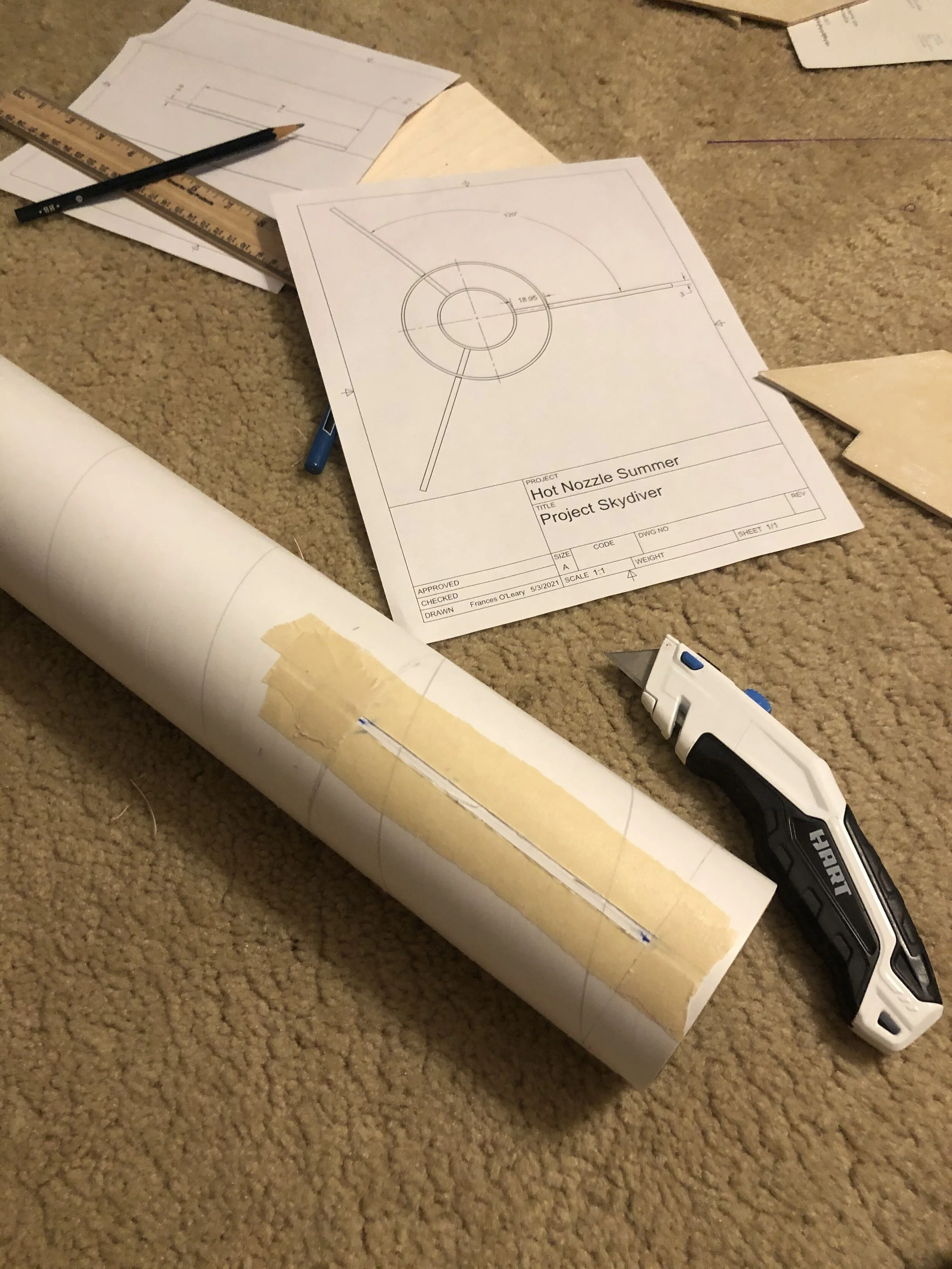
Now that this was done, I just had to cut fin slots in the airframe and insert the assembly while applying epoxy to each of the centering rings. To cut the fin slots I just used a box cutter and Fusion360’s drawing function, which allowed me to print out 1:1 2D drawings directly from my CAD model that I could use as templates. This is shown below:


Once the fin slots were cut I was able to fully integrate both components. Now came the external fillets. These connect the fins and outer airframe effectively, and also act to reduce drag. To do this, I went through the standard process of taping off about 1/4-1/2 inch around each fin, and then applying epoxy. This is something I actually initially struggled with, as epoxy flows quite easily. That means that trying to use it to make rounded and dimensional fillets wasn’t easy, as it would tend to spread and flow instead of hold and stick so to speak. I think this is actually where a lot of excess weight eventually came from; my fin slots weren’t perfect so there were gaps in which the thin epoxy could flow into the space between the airframe and motor mount. This took me several tries to get right, but what I eventually settled on was to mix the epoxy with flour so that it became something analogous to the consistency of peanut butter. This was then easy to sculp fillets with. While I’m sure it probably wasn’t as structurally stable as it should’ve been, it got the job done and I haven’t noticed any problems since.
Once all three fins were fully filleted, all the structural components of the lower airframe were in place and the only thing left to do was make it look pretty. To do this I used a lot of Bondo light-weight auto body filler. This probably also contributed a lot to the total mass of the rocket even though it was marketed as being light-weight. The purpose of the body filler was to fill in the spiral that goes around the body tube, and to also fill in any little marks or imperfections on the fin fillets. This was probably the most time consuming process of the whole project, since I really just wanted Skydiver to look polished and good.


From there, I was ready to paint the whole thing which was really exciting! I went with a grey color for the airframe and then spray painted each fin a different color. The third image from the left above also shows a sneak peak of the nose cone, as well as the body filler that got applied to the bottom airframe section and sanded down.
As for the upper airframe, this just consisted of another section of 3 inch diameter airframe. To this, I epoxied a coupler that I made using an old mailing tube and some fiberglass. Then, I just epoxied in the bulk plate I had CNCed earlier, along with a U-bolt to act as an attachment point. Now all that was left was the nose cone!
To begin, I’ll first explain how the upper airframe goes together. The logic is that the nose cone would slip into the upper airframe and rest there. The nose cone would also have a 1/4 inch threaded rod that was attached to its apex center point, that then runs the length of the upper airframe, and through a hole in the coupler right between the U-bolt attachment points. This would then be fully secured with 2 hex nuts to hold everything together. I realize now that this was a rather circuitous route to take, but it allows for easy vehicle and avionics integration so it all worked out alright.
For the nose cone I also had a decision to make as to what material it would be composed of. On the one hand, I could 3D print it, which would be nice because the dimensions could all be exactly as I modeled them and any specific additions needed for the avionics systems could be easily added. The one issue with this method is the heat however. The melting temperature for most PLA plastics is around 195 degrees Celsius — and that’s its working temperature for a 3D printer! So at even lower temperatures the part could warp or deform just from sitting in the sun on a warm day. This was a real issue for me, as I was planning to launch at the height of a hot and humid Indiana summer just a state over, in Illinois. If my rocket happened to have to sit on the launch pad for a decent length of time, it’s possible the nose cone could deform. Or, if it made it off the launch pad without deforming, I also had concerns regarding its strength. If my rocket happened to take a particularly hard landing after parachute deployment and descent, I would hate for my certification to be halted due to the nose cone being obliterated. This was something I could design for, but when taken with the other risks it seemed like a fools errand to try this.
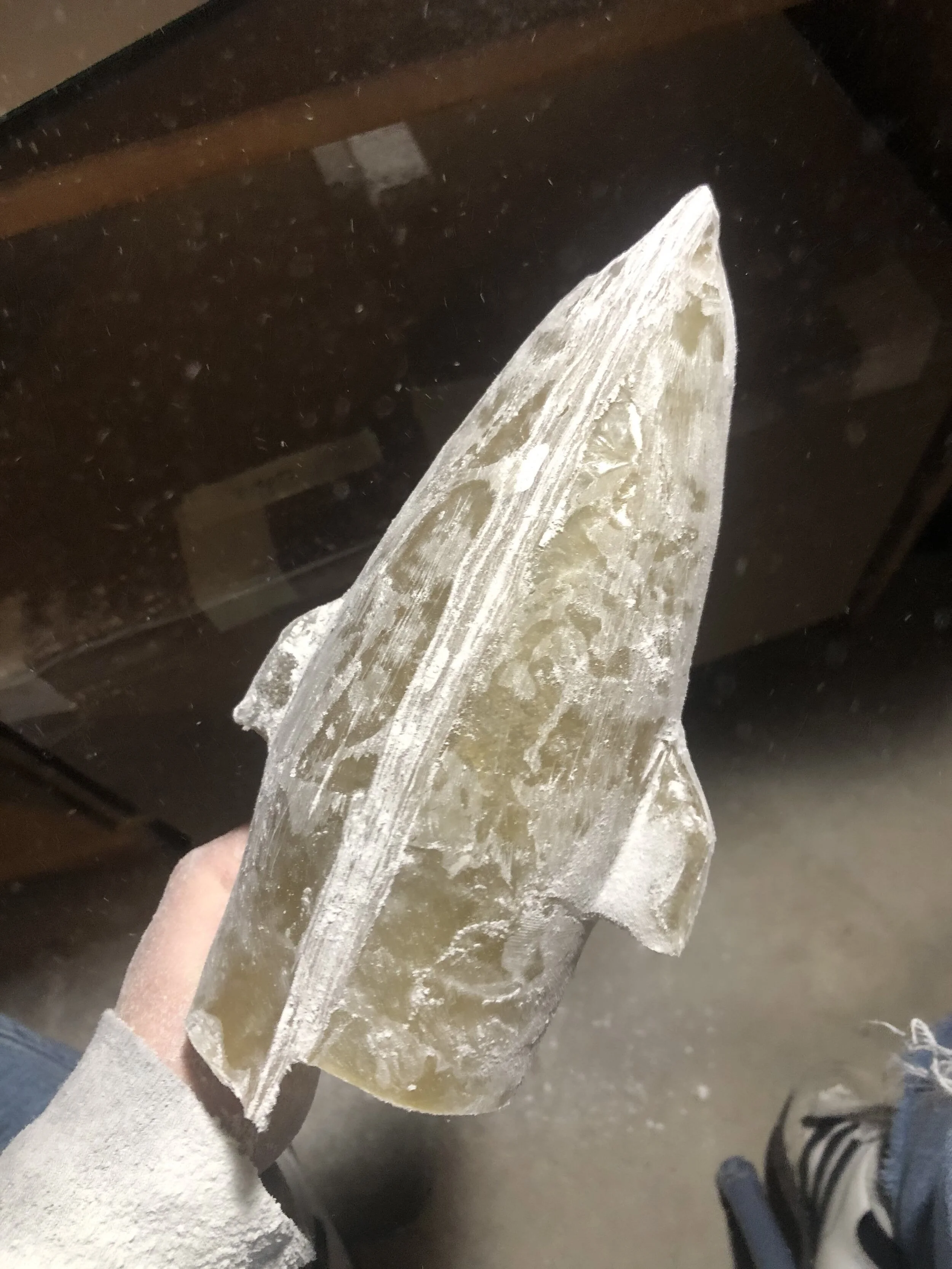
Thankfully I had another option, which was to create a fiberglass nose cone that I could create using 3D printed molds. This way it would definitely hold up to the heat, and probably the impact provided I made it thick enough (I eventually settled upon a thickness of around 2-3 millimeters). This was also great, since I could take my CAD model and just make a couple adjustments so that I could use it as a mold. The idea was to cast two halves of the nose cone, and then bond them together with more fiberglass and epoxy. I ended up going with an outer mold, in which the inside of the nose cone would match the exact dimensions I needed. In hindsight, I’m not sure if this was the best idea, but I went with this route with the priority of the avionics systems in mind, as I wanted to make sure I had enough room for them.
The slideshow below shows the entire process for molding the nose cone from start to finish. I first 3D printed the mold, and then coated it with soy wax as well as some lubricant I found from Lowe’s that was actually meant for wire pulling. From there, I just applied layers of fiberglass and allowed them to dry. I think I did something around 3-4 layers. Once this was done, I could then remove the molded part. At this point, I cleaned it up with a Dremel and cut out the viewing window in the bottom of the canards. The idea for this was that one canard would have a camera, and one canard would have a recording indication LED and ON/OFF switch. Once I had done this to both halves, I bonded them together with epoxy, and then set to finishing the piece. This was a very time consuming process, and took a lot of Dremeling, sanding, and body filler. It was at this point that I also set the 1/4 inch threaded rod in place, by using a pool of epoxy to hold it at the apex center point. Then all that was left to do was paint it!


The nose cone being done marked the final structural piece of the rocket. Now all that was left in terms of construction were the sleds for the camera and data logging systems. With all this done I just finished painting, and applied multiple clear coats to get a nice finish. In addition to this, I got some cool holographic vinyl to cut out the name ‘Skydiver’ to put on the rocket.
To the right is a photo of the finished upper airframe, complete with nose cone! Blue painter’s tape is still on the coupler, but it gives you an idea of how this section goes together, as this upper component then just slides into the lower airframe.
One interesting thing that I did actually forget for the airframe were rail buttons! These are little nylon plastic guides that screw into the rocket and act as the interface between the rocket and the rail that it launches off of. Thankfully however this wasn’t a big deal as I could just go back and add them once the paint was done; I just had to be careful not to scuff anything.
camera system
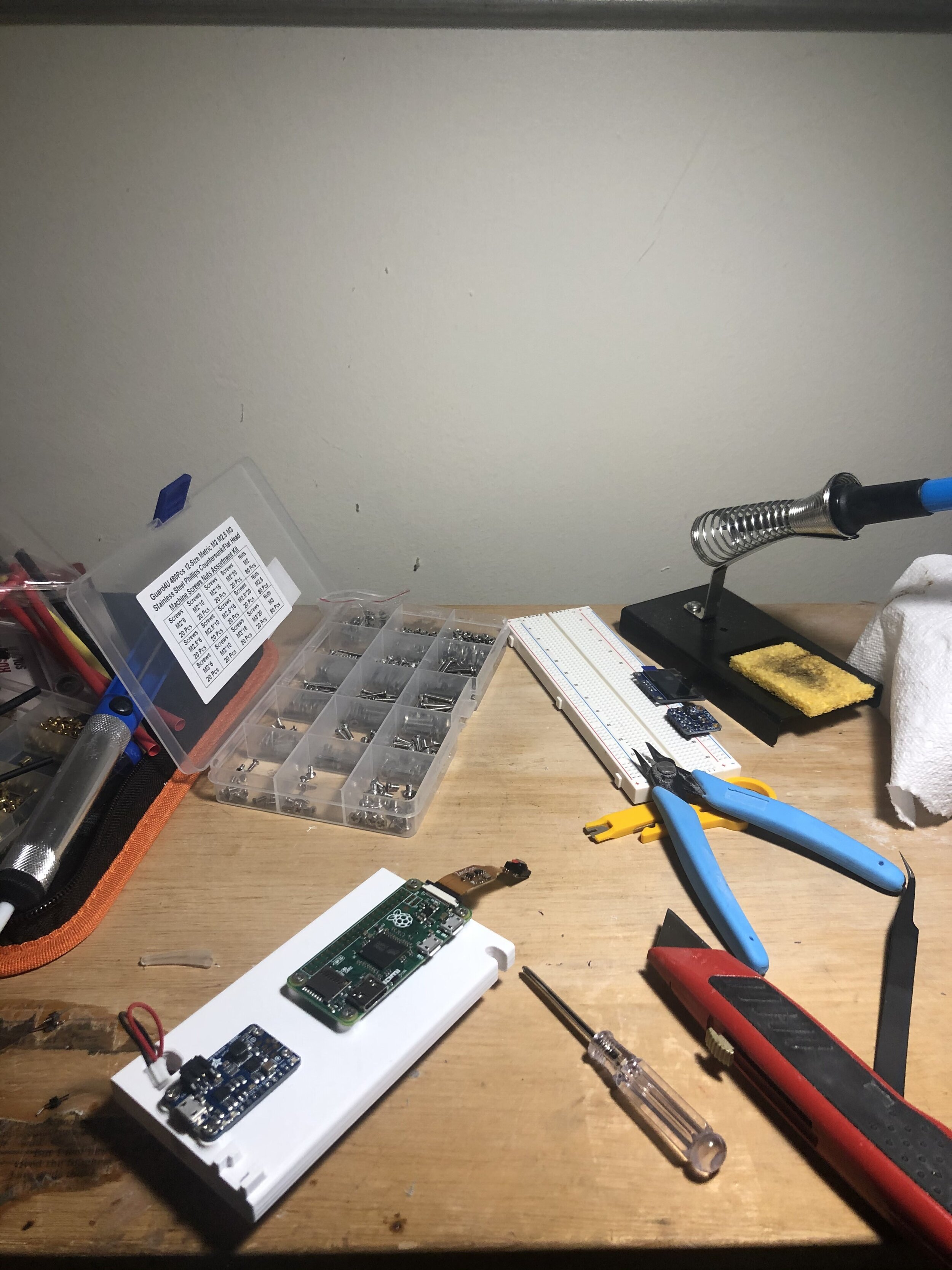
Now it was time for the real fun! One thing I was absolutely set on was filming the launch in some way. While I did have a Gopro I could’ve just strapped to Skydiver, that option was bulky, and in the event of catastrophic failure was an expensive mistake to make. So, as an alternative, I decided to use a Raspberry Pi Zero and corresponding tiny camera that can plug into it, which came in at a whopping $25. This was also very nice, as writing the code to record the video was super simple. All that I did was write a simple Python script that waited until the ‘record’ button was switched, that then initiated a 45 minute recording. It was really rudimentary, but it got the job done, and all that was left to do was tell the Raspberrry Pi to run this script upon booting up. The code, schematic, and sled in CAD are given below:
# Frances O'Leary 23/05/2021
import RPi.GPIO as GPIO
from time import sleep
from picamera import PiCamera
import os

# initialize pins for switch and status LED
GPIO.setwarnings(False)
GPIO.setmode(GPIO.BOARD)
GPIO.setup(11, GPIO.OUT, initial=GPIO.LOW)
GPIO.setup(13, GPIO.IN, pull_up_down=GPIO.PUD_DOWN)

# setup camera and choose unique filename
camera = PiCamera()
files = next(os.walk('/home/pi/Launches/'))[2]
filename = '/home/pi/Launches/Launch_' + str(len(files)) + '.h264'

# logic for switch
init_state = GPIO.input(13)

# check for switch to change state, then record for 45 minutes
while True:
    if GPIO.input(13) != init_state:
        GPIO.output(11, GPIO.HIGH)
        camera.start_recording(filename)
        GPIO.output(11, GPIO.HIGH)
        camera.wait_recording(45 * 60)
        camera.stop_recording()
        GPIO.output(11, GPIO.LOW)
        exit()

Eventually I also experimented with using the os library in Python to begin a raspivid command, and this also worked just fine, so either approach works. Once I had run lots of tests and verified that it worked and amassed lots of footage of my bedroom floor, I designed a simple sled to hold the whole assembly. The sled just uses screws and threaded inserts to hold the whole thing. While it is 3D printed, I wasn’t as concerned about this as I was with the nose cone. If anything happened to befall the camera system it would be sad for me, but wouldn’t impact the certification, and it wasn’t directly exposed to sunlight so I figured it would be alright. This assembly just slides onto the 1/4 inch threaded rod in the nose cone, and is held in place with some side rails. The camera then rests in a 3D printed mount within the canard and is also held in place with screws. Likewise, the recording switch and indication LED have a similar mounting system in the opposite canard. My only regret with this was that the field of view of the camera omits the lower part of the airframe from view, but this is something that can easily fixed in the future. Below are pictures of the assembly process and the fully finished product on the right! The photo on the right also shows the data logger as well, which we will cover in the next section.

data logging
Something else that was very important to me for this flight was to get some good launch data. For this goal I had a strong starting point with my Project Skippy Flight Computer. I basically just made from adjustments to this code, and then designed a new sled to hold the whole assembly. The parts here stayed pretty much the same as in the past, but with a crucial addition of an MPU6050 IMU that allowed me to get some more data relating to the orientation of the rocket and the forces it was experiencing. This was important because in the future I want to use this information to determine which ‘state’ the rocket is in; I want the rocket to be able to know ‘I am ascending’, ‘I am at apogee’, or ‘I am descending’. Getting some readings from a flight would be a great way to start. One caveat is that I was using my old barometric pressure sensor, which gives shaky readings at best and is overall, unreliable for use in flight critical events. Thankfully I wasn’t depending on this sensor to deploy a parachute for example, but in the future I’ll definitely have to find a different barometric pressure sensor to use. The other interesting thing that I found is the difference in temperature sensing; this wasn’t flight critical but just something I thought was neat. Below is a plot of some temperature readings from the MPU6050 and my barometric pressure sensor. You can see they are fairly consistent, but differ by about 4 degrees.

Below is the code that drives the data logging. Note that this works similarly to the camera system, in which it has no knowledge of the flight and just logs for a set amount of time. In the future I want to change this to depend on the state determination functionality of the flight computer, so that it can recognize when it has launched and only start recording data and video then. In theory this shouldn’t be too hard, especially with the inclusion of an onboard accelerometer in the MPU6050, but I wanted to play it safe on this flight. Also below is the CAD for the sled mount.
/*
 * Frances O'Leary 5/24/2021
 *
 * This is code for project skydiver, which is
 * my homemade and scratch designed level 1 certification
 * rocket. It is essentially a data logger that is used
 * to record data as the flight occurs.
 *
 * NOTE: This records purely raw data for further
 * analysis.
 *
 * Flow:
 *  - turn on device
 *  - if all goes well, green LED will turn on
 *  - device logs data for 45 minutes
 *  - logging stops (green LED off)
 *  - file closed
 *  - sketch terminates
 */

#include <SPI.h>
#include <SD.h>
#include <Wire.h>
#include <Adafruit_Sensor.h>
#include <TinyWireM.h>
#include <USI_TWI_Master.h>
#include <Adafruit_MPL3115A2.h>
#include <Adafruit_MPU6050.h>

#define cardSelect 4
#define loggingLED 11
#define redLED 13

Adafruit_MPU6050 accelGyro = Adafruit_MPU6050();
Adafruit_MPL3115A2 pressureSensor = Adafruit_MPL3115A2();
File logfile;
char filename[20];
float dataLoggingStartTime;

// data definitions
float time; // seconds
float pressure; // pascals
float altitude; // meters
float temperature; // degrees C
float xAcceleration; // m/s^2
float yAcceleration; // m/s^2
float zAcceleration; // m/s^2
float xGyro; // rad/s
float yGyro; // rad/s
float zGyro; // rad/s
float mpuTemp; // degrees C

// begin flight setup
void setup() {

  // set pins
  delay(500);
  pinMode(redLED, OUTPUT);
  pinMode(loggingLED, OUTPUT);
  digitalWrite(loggingLED, LOW);
  digitalWrite(redLED, LOW);

  // see if card can be initialized
  if (!SD.begin(cardSelect)) {
    digitalWrite(redLED, HIGH);
    return;
  }

  // create filename that will not overwrite other flight data
  strcpy(filename, "/FLIGHT00.csv");
  for (uint8_t i = 0; i < 100; i++) {
    filename[7] = '0' + i/10;
    filename[8] = '0' + i%10;
    if (! SD.exists(filename)) {
      break;
    }
  }

  // attempt to open the file
  logfile = SD.open(filename, FILE_WRITE);
  if(!logfile) {
    digitalWrite(redLED, HIGH);
    return;
  }

  // write data schema on top line of file
logfile.println("time(sec),pressure(pa),altitude(m),temperature(C),xAcceleration(m/s^2),yAcceleration(m/s^2),zAcceleration(m/s^2),xRot(rad/s),yRot(rad/s),zRot(rad/s),mpuTemp(C)");

  // attempt to connect to acceleromter at I2C address 0x18
  if (!accelGyro.begin()) {
    digitalWrite(redLED, HIGH);
    return;
  }

  // set acceleromteter and gyro range to max
  accelGyro.setAccelerometerRange(MPU6050_RANGE_16_G);
  accelGyro.setGyroRange(MPU6050_RANGE_2000_DEG);
  accelGyro.setFilterBandwidth(MPU6050_BAND_21_HZ);

  // attempt to connect to pressure sensor
  if (!pressureSensor.begin()) {
    digitalWrite(redLED, HIGH);
    return;
  }

  // get base time
  dataLoggingStartTime = millis();

  // set LED to 'logging mode' (aka on)
  digitalWrite(loggingLED, HIGH);

  //Serial.println("Init success!");
}

void loop() {
  // get data
  time = (float)(millis() - dataLoggingStartTime) / 1000.0; // convert to seconds
  sensors_event_t a, g, temp;
  accelGyro.getEvent(&a, &g, &temp);
  xAcceleration = a.acceleration.x;
  yAcceleration = a.acceleration.y;
  zAcceleration = a.acceleration.z;
  xGyro = g.gyro.x;
  yGyro = g.gyro.y;
  zGyro = g.gyro.z;
  mpuTemp = temp.temperature;
  pressure = pressureSensor.getPressure();
  pressure = pressureSensor.getPressure();
  altitude = pressureSensor.getAltitude();
  altitude = pressureSensor.getAltitude();
  temperature = pressureSensor.getTemperature();
  temperature = pressureSensor.getTemperature();

  // print data to file in predefined data schema
  logfile.print(time);
  logfile.print(",");
  logfile.print(pressure);
  logfile.print(",");
  logfile.print(altitude);
  logfile.print(",");
  logfile.print(temperature);
  logfile.print(",");
  logfile.print(xAcceleration);
  logfile.print(",");
  logfile.print(yAcceleration);
  logfile.print(",");
  logfile.print(zAcceleration);
  logfile.print(",");
  logfile.print(xGyro);
  logfile.print(",");
  logfile.print(yGyro);
  logfile.print(",");
  logfile.print(zGyro);
  logfile.print(",");
  logfile.print(mpuTemp);
  logfile.print('\n');

  // end data capture after 60 minutes
  if (time >= 3600.0) {
    logfile.close();
    digitalWrite(loggingLED, LOW);
    return;
  }

  delay(100);
}
Data logger CAD.
You can see that the datalogger sled has a little shelf for the MPU6050 so I don’t have to transform any readings. One caveat is that I was not able to center it exactly on the rocket given the 1/4 inch threaded rod. Now that I had all of my systems prepared, and the whole structure completed and painted, I was ready for launch day!
launch and recovery
To launch my rocket, I went to Princeton, Illinois for Quad City Rocketry’s summer event called Mini Midwest Power (May 29th) with my boyfriend, who was also getting his L1. Once we got there, we saw some really cool rockets launch, like a giant green monster that got caught in some power lines near the launch site. We also realized that we did not know a thing about how to actually launch our rockets, or what the protocols were. We walked back and forth from the car to the registration table, gathering little bits of information along the way. We figured out which forms we actually needed to get our L1’s, and found Tim, the ‘Wildman’, who sells motors. It was after we made the mistake of buying reusable (which require a casing) and not single-use motors that we realized we might be just a little bit out of our element. Thankfully though, someone recognized my jacket, which had a Purdue Computer Science emblem stitched into it, and he approached us to say ‘Hi’ since he was from the Indiana Rocketry Association which holds some launches right near Purdue! Without him I probably would not have had a successful launch. He showed me how to prepare my motor and drill my delay, which I had calculated using OpenRocket. He also told us about the different protocols for setting our rockets up on the launch pad, and how to do everything. He was just a big help and I’m thankful he approached us.
To alleviate my own fears, I had made the preflight checklist below to make sure I remembered to turn on all of my systems:

Preflight Checklist. Note that the motor delay is for an I180, not for the H219 I ended up using.
Now, all that was left to do was launch! Below is some launch pad footage of Skydiver coming off the rail, as well as the full video that my camera system recorded:
In the end, I was ecstatic at how the launch went! I was able to successfully recover my rocket and get my L1 certification which made my day. Skydiver flew to an apogee of 1439.8950 feet, as recorded by my data logging system on an Aerotech H219 single-use motor. This was neat because it was very close to what OpenRocket had projected for Skydiver’s apogee with this motor. I couldn’t have asked for anything to go better, all things considered, and I even got some cool data! Below are some plots of the data I got back from the flight:


As you can see from the plots above, the motor ignited and Skydiver launched at T+47.28 seconds. I realize using the T+ convention in this way might be improper, but it’s the easiest way to describe what is going on in these plots. Along with launch and initial ascent, we notice a maximum total acceleration of 145 meters per second squared at T+48.97 seconds. Looking at acceleration across the different axes, we can notice that we see that the maximum acceleration for the z axis on ascent was 142 meters per second squared. You can see we then reached our peak altitude or apogee at T+54.03 seconds, and at this point the accelerations in all axes dropped to zero as the rocket experienced momentary weightlessness. Notice that it is at this point that the rates of angular rotation start to sky-rocket. This is because after Skydiver reached apogee, we saw the main parachute deploy at T+55.72 seconds, at which point the upper airframe which housed the data logger began to swing wildly from its shock cord that was attached to the main chute, which accounts for the crazy rates of angular rotation that are shown after this time stamp. In addition to this, we notice as the data logger hangs downwards from the shock cord and parachute that we see a strong z acceleration. At T+167.20 seconds Skydiver landed on the ground, and was dragged a little bit by wind until T+172.2 seconds at which Skydiver came to a full stop.
I’m very glad I put these sensors on the rocket because it was so cool to look at the data and see it line up with the flight I saw in person. Like the rate of descent as shown by the altitude plot, or how you can pick out different key events by looking at the acceleration and angular rotation plots. It’s just really cool and I love looking at all the data.
What I would do differently
In the process of writing this, I mentioned a lot of little things I would’ve done differently:
take more care with the fillets
use a better barometric pressure sensor
include the lower airframe in the field of view of the camera system
Other things I would improve upon include:
learn more about the sensors I am using and filter the data that they give
using a state system to determine when to perform actions, such as data logging
Overall however, I think that this was a great learning experience and starting point for me in high power rocketry, and I can’t wait to build more systems and launch more rockets!
Finally, below are some more pictures. My boyfriend and I were able to go to Chicago afterwards and have a nice celebration dinner; he got his L1 too! Thank you for reading!


