stewie the stewart platform
8:12 AM on Friday, March 26th, 2021 (West Lafayette, IN) - TBA
As a note: this project is currently in progress and I plan to document it in an entry-style project journal as it progresses. Enjoy!
INitial planning - March 2021

So, who is Stewart and what’s he doing with a platform named after him? Basically, one guy named D. Stewart back in 1965 wrote a paper about these wonderful platforms that can move within six degrees of freedom. Almost simultaneously however, Eric Gough and Klaus Cappel also developed machines very similar to the one Stewart described, so there is some debate as to what is the most apt name for the device. I will refer to it as a Stewart platform because it makes for the most-cute project name: Stewie.
You can think of a Stewart platform as a plane in space that can be manipulated by six rotary or linear actuators. The idea is that by moving these six actuators in unison, different configurations of the platform can be achieved. An example of a Stewart platform utilizing linear actuators is shown to the right. A common application of such platforms are telescopes that track certain spots in the sky, flight simulators, and popular 4D rides at attraction parks such as Disneyland and Universal Studios. I originally got the idea to construct such a platform after seeing one in action in the following YouTube video:
In this video, Shane Wighton constructs a robotic pool cue that uses computer vision and a little bit of geometry to ensure that you never miss a shot while playing pool, and can also make some especially challenging shots. The part that really caught my eye about this project(besides the bugs he overcame with normalizing the overhead image of the pool table so it could accurately compute shots) was the tiny Stewart platform he uses at the end of the cue to manipulate its angle and position. It’s just a really neat piece of engineering on top of an already awesome project, and I just knew I had to make one.
This also goes pretty perfectly with the courses I’ve taken thus far, as I get to apply what I’ve learned in such classes as Computational Kinematics, Computational Geometry, Vector Calculus, Linear Algebra, and Numerical Methods.
Speaking of Computational Kinematics, this is actually my final project! For the past semester I’ve been engaged in a variable title course I created with Professor Elisha Sacks that takes a deep dive into his and Leo Joskowicz’s book The Configuration Space Method for Kinematic Design of Mechanisms. Below are write-ups concerning the topics we discuss if you are interested in reading them, as they kind of explain the lens with which I’ve been viewing this project. When I was originally creating the syllabus for this course, I had thought I would conduct a comprehensive kinematic analysis on a cycloidal drive as my final project, but since seeing Shane’s video I haven’t been able to get the idea of a Stewart platform our of my head.

An excerpt from General Planar and Spatial Pair Feature Contact.
Week 3: Kinematic Pairs and the Configuration Space, Classifications of Mechanisms
Week 4: Simple Planar Feature Contact
Week 6: Partition of Configuration Space
Week 7: Partition Algorithms
Week 8: Analysis and Simulation
Week 9: Tolerancing
Week 10: Synthesis

So, how does one construct a Stewart platform? This was the exact question I was having. It’s all nice to dream about a Stewart platform but when it came to the initial design I was a little stumped. Using linear actuators greatly simplifies the math involved in manipulating such a platform, but rotary action servo motors are much cheaper, and the computer will be doing the calculations so what is there to lose? The other point of consideration was the shape of the platform, and the connections between the linkages and base/platform. Some Stewart platforms use universal joints, some use ball joints; this was another question of cost vs effectiveness.
A simplified version of a rotary Stewart platform is shown to the left. It consists of three main groups of components: the base(yellow), the platform(blue), and the linkages(red/black).
Now that I knew the basic components I needed, and the options I had cost-wise, I was ready to start assembling the workings of Stewie. I chose to go with rotary servo motors as my form of actuation since I am a college student and servo motors cost less than linear actuators. In addition to this, the extra math also poses an interesting computational challenge.
I also chose to use ball joints instead of universal joints because they are far more cost effective. For the base and top, I figured I would just model them in Fusion 360 since 3D printing the parts would be way easier for me than fabricating them in any other way. Finally, I chose an Arduino Mega 2560 to power the whole setup since I had an extra one lying around. Granted, I haven’t gotten to the actual coding part so this is subject to change if I figure out that a different board is better for this application. A full list of parts is given below:
1.75 mm PLA Filament
Now that I had a general idea for my Stewart platform and parts list, all that was left was to model it in Fusion 360.
modeling and design - march 2021
When I was initially designing this, I began by looking at different websites and papers detailing the basics of Stewart platforms that utilize rotary actuation, and I concluded that as long as the basic laws of its construction are abided by, if it looks like a Stewart platform, it will work like a Stewart platform. While this didn’t make the task any easier, it gave me confidence in diving into the project and just seeing what worked and what didn’t. I’m lucky in that fabrication with 3D printers is relatively cheap and fast, so I went through a lot of prototyping.
This was also my first time really working with components in Fusion 360 as opposed to just bodies, so to start I began with modeling an MG996R servo. This was very useful because I could essentially construct all my ideas virtually and then see if they worked in real life. In addition to this, I did a lot of tolerance tests on my Ender 3, such as the screw test shown below. This was to ensure that once I printed the bigger parts like the base later on, I could be sure the tolerances were correct for the screws and I wouldn’t have to print them multiple times.

My MG996R servo model.

One of my tolerance tests.

Stewie’s base bottom.
By this point, only the servo motors had come in, so I set out constructing the base. The most common construction I’ve seen in my research for the geometric construction of a base and the placement of the servos was a method detailed here in which two concentric circles are drawn and are both circumscribed by an equilateral triangle. These intersections then dictate the basic outline of the base. From here, I placed the mounts for the servo motors around the base such that I would have room for 40 mm long servo horns. This measurement is somewhat arbitrary, but I picked it since it would allow for a decent number of different configurations for the platform, and meant the whole set up would be nearly perfectly sized for printing on my Ender 3.
The base is shown to the right; as you can see it has six slots for the six servo motors. Originally I did not have the stabilizing walls between them, but after printing test sections I decided this, along with fully supporting them along their base, was necessary. Each slot also has holes for two M4 screws which hold each motor in place.

Stewie’s base top.
After constructing the base and doing multiple test prints(one time I exported it without my new modifications!), I essentially mirrored the component to create the base top.
This component is shown to the left. The key change I made here was reducing the amount of material that was previously utilized for supporting the ends of the servos as well as their sides. By increasing the stability of the base, I found that having a top component that simply held the tops of the six servo motors static was more than sufficient. When all of the screws are in place I can guarantee this thing is not going anywhere.
One critical part not shown in the base is storage for the Arduino Mega 2560, and cable management. In this iteration I decided that I would focus on perfecting the basic structure, and then figure out how to integrate the board and wire management later. This is also why the parts you will see later on are all printed in random colors; since they were just prototype components I printed them with any and all filament I had.
By this time in my planning, the other components had come; namely the ball joints and stainless steel rods. With these new components in hand and the base pretty much read to go, I moved on to designing the modified servo horns that would connect the linkages to the motors. One nice thing about the servo motors I got is that they each came with an array of injection molded servo horns of varying shapes. These were really nice since they precisely fit the output gear on the motor, which had too fine of an amount of detail to print with an FDM printer. Because of this, I decided to integrate these injection molded servo horns into my design so I wouldn’t have to figure out another coupling method(such as tensioning screws, etc). I arbitrarily chose the circular servo horns because they had the smallest radius, and I figured they would be easy to pop in and out of 3D printed parts as I continued testing. My main concerns for this part were that the default circular servo horn be dependably attached to the 3D printed component, and that the ball joint was able to screw in to the end and still move freely. The final model for this part is shown below:

The modified servo horn model.
This also required various iterations of the design due to tolerancing issues concerning the hole for the M3 mount for the ball joint, as well as the snap-fit for the injection molded servo horn. In the end though in practice I believe the design will be dependable enough, although later on the injection molded servo horn may need to be superglued into place, and I might modify the design to look sleeker and use less material. Also note that any empty recesses indicate a screw that will eventually go there, such as in the case of the central hole on the servo horn, and the central hole on the ball joint in the figure to the right.

The modified servo horn shown with the injection molded component and ball joint with threaded linkage.

Stewie’s platform.
Now that pretty much everything was modeled, I just needed to construct the actual platform that made Stewart so famous. Throughout my research I found that the actual platform could be smaller or larger than the base, within reason and taking into account the limitations of the joints used on the linkages. Due to this, I went with the standard option of making the platform pretty much the same size as the base. To save material, I designed it to be as minimal as it could while maintaining structural integrity. It secures to the linkages similarly to how the ball joints connect to the modified servo horn; they just screw in using an M3 screw. The final platform model for this iteration is shown to the left.
Now that I had all the components together, I simply unified them in one common model. This and an interesting section analysis are shown below. Note that some parts(most notably the ball joints and the platform) do not exactly line up. This is due to my green-ness to components in Fusion 360 and is something I hope to fix in the future.

The full model of Stewie 1.0!

An interesting cross section of Stewie shown
Now that Stewie 1.0 was all modeled and ready, I began 3D printing him. This is all depicted in the gallery below. There were some hiccups and I ran low on contiguous filament but he came out anyway! He is now fully assembled, and I am finally ready to begin coding him and testing out how he moves. I think besides the math being quite interesting with the rotary actuators, I am interested to see what structural bugs arise from the actual platform construction as I am certainly no mechanical engineer.


Assembled Stewie 1.0 sans computational ability!
coding movement - April 2021
It is now about one week later and some progress has been made with Stewie! My main focus this past week has been to do my due diligence and make sure that everything is wired up appropriately and is receiving the proper current/voltage. Especially for the servo motors, this is very important since their function and accuracy are at the heart of this project. Therefore, my first step was to work with a single motor, and become familiar with the Arduino servo library, Servo.h. I’ve used it in a couple other projects, but never enough to actually read the documentation, which is about what you would imagine since the library consists of fewer than 10 functions total. But it went off without a hitch, and I was able to use a joystick to play around with a servo and make sure the setup worked, since this project is basically just this functionality six times over. My testing code is below, as well as a video of the motion which is pretty simple but was a nice stepping stone in the project process. All of this code can be found in a repository I will link here later once the project is all done.
// include the Servo library
#include <Servo.h>

// declare pins
int servoPin = 2;
int switchPin = 23;
int xPin = 0;
int yPin = 1;

// Create a servo object
Servo Servo1;

// setup loop
void setup() {
   // attach the servo to the pin
   Servo1.attach(servoPin);
   // begin output
   Serial.begin(9600);

   // setup joystick
   pinMode(switchPin, INPUT);
   digitalWrite(switchPin, HIGH);
}
void loop(){
   // capture values
   int switchVal = digitalRead(switchPin);
   int xVal = analogRead(xPin);
   int yVal = analogRead(yPin);

   // print values for debugging purposes
   Serial.print("Switch: ");
   Serial.print(switchVal);
   Serial.print("\nX-AXIS: ");
   Serial.print(xVal);
   Serial.print("\nY-AXIS: ");
   Serial.print(yVal);
   Serial.print("\n\n");

   // compute servo offset from joystick value
   // the analog pins report a value of 0-1023 from the joystick
   // so we map these values to a range of 0 to 180
   Servo1.write((((double) 180 / 1023) * xVal));
   delay(200);
}
The video above also shows the recently printed Stewie case for the electronics! Or at least the main board. Later on this will all be integrated into the design of the full platform, but for now I just needed a case so it wouldn’t slide around my desk.
One interesting thing I’ve encountered is that the servos do not seem to turn within their full range. For example, an input of 90 degrees might work and visually appear to be about 90 degrees, but an input of 180 degrees would visually appear to be a change from 0 degrees of about 160-170 degrees. I tried playing around with other servo methods to rectify this, but I couldn’t get it so for now I think I will focus on the general motion and really try to dial in the settings later on.
The other interesting thing is that the servos need a power supply external to the Arduino. This isn’t a big deal, but I think it will allow me the opportunity to add some fun lights and other features later on.

Now that I knew the basic setup worked, I just extrapolated it to the six servo usage case. Interestingly enough the hardest part of this was wiring the whole thing. I think in the future I will definitely have to think of a way to contain the wires in an orderly fashion that allows for easy fixes but keeps them out of the way.

A general wiring schematic for Stewie. (open in a new tab to view the notes)

Stewie fully wired up!
Now that Stewie was wired up, I began coding. There were some interesting considerations along the way that I had failed to think of before, such as that I would need to do a little bit of math for all of the servos on the right, which have a servo horn facing west. This is interesting with the servo library, as you cannot specify a negative degree value. This isn’t a challenging problem; just subtract the value from 180 instead of passing it in but it was something I never thought about so it was interesting when I ran into it. I also figured out that the friction fit between the injection molded servo horns and the 3D printed ones might not be strong enough; these parts will likely be superglued into place for the final iteration.
I knew before I went crazy coding and dived right in, it would be a good idea to dip my toes into the inverse kinematics waters by just trying some simple goals like getting the platform to move up and down with input from the joystick. This way I could debug and learn a little bit along the way instead of coding everything without running it, plugging it in, and watching in horror as Stewie ripped himself apart. So, my first step was to zero all of the motors on the left of each group(it might be hard to make out, but the pink post-its in the picture above mark groups A, B, and C), and then to set all of the motors on the right to 180. This way they were calibrated such that my frame of reference matched what I was thinking I was doing in my code. Thus, a degree of 90 tells the servos on both sides to stick out perpendicularly, so the platform is in its ‘steady state’; perfectly level(ish) and mid-height, as pictured above. With the servos calibrated, I then attached the servo horns again and thus the platform. Now I was ready for my first test.
My first goal was just to get the platform moving up and down like I said before; I would be happy with any movement that didn’t break anything. So, like my initial test with the joystick, I just made the code so that they all moved the desired angle(or 180 minus that angle if they lie on the right side). This way I could use the joystick to raise the platform up and down. Although in doing this I realized that I found my first modification to be made to the base; the distance from the bottom to the centerpoint of the servo shaft is less than 40 mm! Since the adapted servo horns are 40 mm from shaft centerpoint to ball joint centerpoint, I currently do not have the full set of possible configurations available to me. This means that if I set all the servos to point straight down, they would strike the table before they got there. This isn’t a big deal, as I can just account for this with code during testing so it can’t access that range, or even prop it up on something, but it was cool to start noting little ways I can make improvements and things I hadn’t caught before.
So, with everything wired up, I was read for my first test! Here are the results:
Well. . . that didn’t go quite as I thought! You probably noticed how its motion is not smooth and continuous. Rather, each servo moves sequentially. This was something I had not accounted for, but makes perfect sense looking at the code. The lines are pretty much: Servo One Move x Degrees, Servo Two Move x Degrees, and so on and so forth. So the Arduino does its perfect job of dispatching these commands, but they result in this unfortunate motion. The platform still moves, but it does so in a stilted way.
My first idea was to fix this with multithreading. I would simply start each thread and dispatch it to tell its respective servo motor how many degrees to move. But this had a couple issues: what if each servo is dispatched a different number of degrees, say one has to move 10 degrees and another 160? This would certainly happen for complex movements, and would still result in a stilted motion, because the 10 degree motion would execute 16 times faster than the 160 degree motion if they occur at constant rates. The other issue was even worse: the Arduino Mega has one core, so I don’t even have the option of using threads.
By this point I was up a couple creeks with no paddles in sight, so I turned to Google, where I found a common solution is to interleave the motions of the servos and scale them to finish when you want them. So, you might have a for loop that moves the 160 degree servo 1 degree every 5 milliseconds, at which point it will move the 10 degree servo 1 degree for every 16 the other one does. However, this still posed some problems, such as a slowdown that is observed across just two servos. I didn’t test it out but I had a hunch that even if I did my best job of interleaving the motions, six servos might still be too much for smooth, fast, and continuous motion.
So, instead of fixing it with code I went the hardware route because I want the motion to be as smooth and fast as possible, which means the commands to the servos would be dispatched as close to simultaneously as they could be. To do this, I decided to use this servo motor driver board, which has gotten good reviews and should hopefully be the perfect fix to my problem. It should be coming in the mail in a couple of days, so in the mean time I’m working on reading up more on the actual inverse kinematics for the platform, and other things I need to fix. The most notable are:
ensure stability of the platform(specifically the linkages from the base to the platform)
fix the base height and add rubber feet for stability
look into servo libraries or techniques for scaling the speed of servo movements to address the 10 degree-160 degree problem
either adapt friction fit on the servo horns or superglue the final versions in
work on the inverse kinematics code
screw in the servo horns, as currently after lots of motion they tend to slide off
I’ll report back soon!
diving into inverse kinematics
In a nutshell, inverse kinematics is like telling a robot “hey, I want to do this”, at which point the robot thinks “in what way can I manipulate my motors to achieve that configuration?”. Or something along those lines. For Stewie, it means that when I tell him to orient his platform 18 mm below his standard z axis, and roll -15 degrees around his x axis, he has all the information he needs to perform such a maneuver. Interestingly enough, this is easily achieved using some basic linear algebra and vector notation. The idea is that the user or program will feed Stewie a coordinate and rotation relative to his platform coordinate space. From there, this point can be used to translate and manipulate the coordinate space of the platform. Then, we can generate a rotation matrix and a translation matrix, that represent the translation and rotation to transform the origin of the base coordinate space, to the newly transformed platform coordinate space. Now all that is left is to subtract each transformed platform vector from its corresponding base vector. Now, if we take the magnitude of this vector, we have the length we need for the ‘arms’ of the Stewart platform to extend to.
To make this process easier to think about, I grouped the servos accordingly to which side of Stewie they lie upon. With six servos, that gives us three groups of two. Thus we have Group A, Group B, and Group C, and each group has a left and a right servo motor. This gives us the really nice notation of Group-Side, so that we have servos AL, AR, BL, BR, CL, and CR. This notation will be used in pretty much all of the code from here on out. Now that I had an easy way to reference each servo, I went about the task of going back into Fusion 360 and obtaining the standard platform and base vectors for each servo. For the base vectors, this is the distance from the base origin to the servo rotation point, and for the platform vectors, this is the distance from the platform origin to the attachment point. These vectors are shown in the figures below:

Stewie Base Vectors

Stewie Platform Vectors
After this, I went noted the values per vector in Matlab, and began with some basic math. I chose Matlab because it provided an easy way to perform the calculations I wanted to, and reduced the math so that I could be sure my inverse kinematic model was correct before writing code for Stewie. This code is given below as a screenshot, but is also available on the Stewie GitHub page:
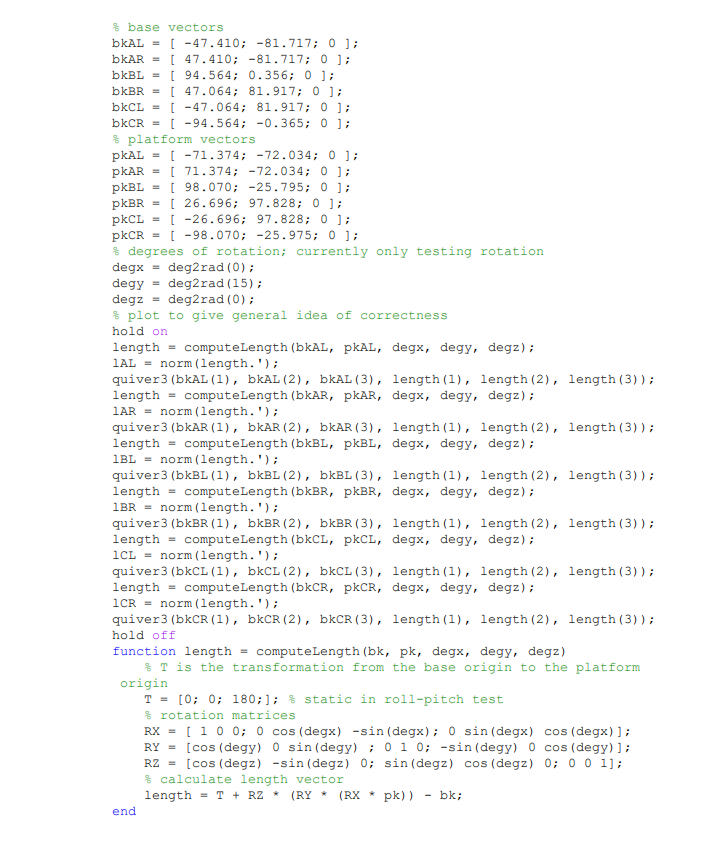
Matlab code to verify length calculations.

The resultant simplistic plot from a rotation of 15 degrees about the x axis.
As you can see, the plot generated is very simple, but it helped me to verify all my math was correct and that things looked about right. The main bit of importance is actually the calculation to compute the length vector, which is shown to the left. That one line shows the rotations being applied to the given platform vector, and then having the base vector subtracted from it and the whole thing being transformed. If this were a Stewart platform with linear actuators, we would be done!
But good linear actuators are expensive, and 3D printing my own seemed like it might be a project within a project. So, as you know, we are using rotary action servo motors. So how do we use this length to obtain an angle of rotation for our servo motor? As you might imagine, it involves just a bit more math:
Interestingly enough, the only additional bit of information that we really need is the degree that each servo is rotated about the base origin in the xy plane. These angles(in degrees) are given in the diagram below:

The angles per servo.
So, now we have these angles, but how do they actually help us?
The main idea is that using some trigonometry, you can figure out the angle that the servo must move to in order for the vertical displacement to be equal to the desired length, if you know these rotations, the length of the servo horn, and the length of the rod. In our case, the total length of the rod from servo horn attachment to platform attachment is 185 mm, and the distance from the center of rotation of the servo to the attachment point on the servo horn is 40 mm.
And so basically, you can use these fixed components along with your calculated length, taking into account the rotation of the servo relative to the base, and come up with a pretty nifty and simple calculation for the number of degrees either above or below the horizontal each servo must be rotated in order for the platform to achieve its desired transformation and rotation.
Like I did with the example that just calculated the length, I also put this version into Matlab in order to verify my results. Additionally, a drawing that shows how the components work together is also given:
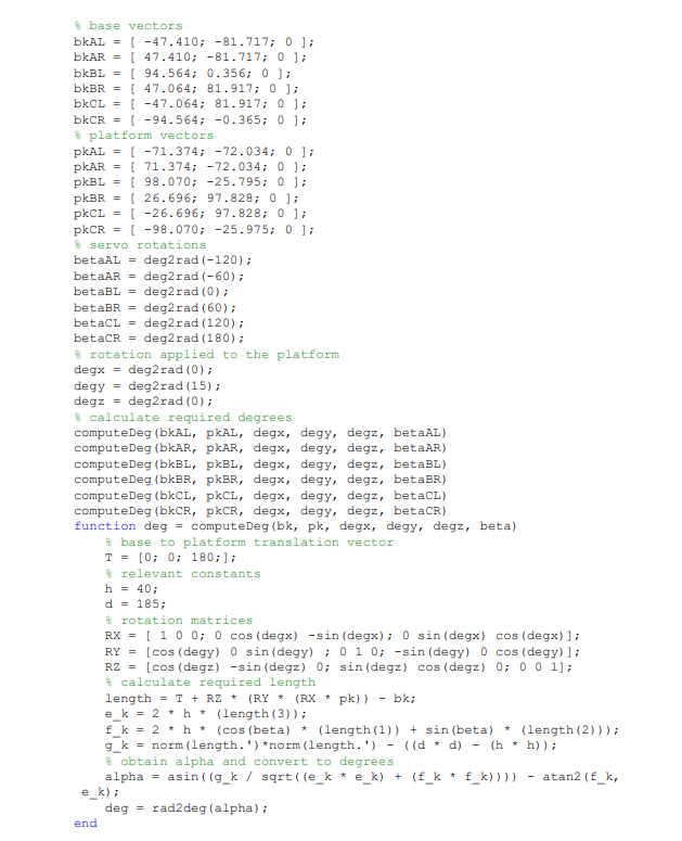
The Matlab code to calculate the required angle.

A visual representation of the parameters needed to calculate the angle alpha.
Note that for this code I didn’t plot the arms because I didn’t really find it necessary after the last test, and that this is just a pure rotational test. This is because as it currently stands, I only have one joy stick I can hook up to my Arduino. Thus I only have two degrees of freedom, so my first instinct was to do a pitch-roll test since that could verify my inverse kinematic model and would be relatively simple to debug and implement. So, without further ado, I present to you Stewie’s first pitch-roll test!
So that didn’t go as expected. . . after some debugging, I got even more confused. It seemed like as Stewie was on, some form of error was accumulating and all the degree values were converging to NaN which was very bad. What I then realized was that my code was actually modifying the base vectors, and storing those modified values to be used in the next run. Thus, from Stewie’s point of view, he thought he was moving, but he actually wasn’t, so all his calculations thereafter were very off.
After fixing that, I had high hopes the program would work, so I uploaded the fixed code, and attempted rotating about the y axis, which worked perfectly! He could fully rotate -15 or +15 degrees about the y axis with no problems. Then I went to try the x axis and he translated instead of rotated. This problem had me very confused for quite a while. It got to the point where I was crawling through the code, verifying it in Matlab, and then continuing. All of the calculations were right so I was completely puzzled. And then I realized, I was actually calculating all of the necessary degrees perfectly, but when it came time to write them to the servos, it almost seemed like they were going out at random. The calculated angle for servo CL was going to BR, and just everything was messed up. This was an easy fix thankfully but I still have no idea how something so bad ended up in my code. After that, the inverse kinematic model was done! So once again I loaded the code and here are the results, with the correct kinematic model on the right, and the odd translation problem on the left:
But, you might notice, Stewie takes a really really long time to react. Almost something on the order of seconds. Stay tuned for this in the next installment!
print statements and slow motors
So, now the problem was that everything was seemingly working as intended, but the reaction time was extremely slow. It took around one second for input from my joystick to work, and that just wasn’t going to cut it. Like I said in an earlier portion of this project, I got the PCA9685 servo driver board in the hopes that it would alleviate my servo timing issues and make them appear concurrent. However, as you can see from the initial test to the right, that didn’t exactly happen. The example to the right is still actually using the vertical test, and shows the delayed reactions across servos, like in the roll-pitch test above. My initial thought was that I could possibly alter the frequency that the board was operating at in order to speed it up. Since this was my first real experience with programming PWM signals, I was kind of flying upside-down and was willing to try anything. However, after trying multiple different frequencies, nothing worked. So, I decided to go back to basics, since I had seen many other peoples’ Stewart platforms on YouTube that utilized no special external boards and just seemed to work, even on Arduino Uno’s and much smaller boards than I was using.
So, I modified my pitch-roll test code to utilize the standard servo library after doing some initial small scale tests to find the bounds for the writeMicroseconds() method. After I found the appropriate bounds for my servos, I fully implemented it and ran it in the pitch-roll test with high hopes. . .
That were immediately dashed when the same slow result was observed. So, I went back to basics and hooked up just two servos and tried sending simultaneous different rotations to each one. And, it seemed to work perfectly, despite one of the servos being attached to my prototype for a rocket roll control system. This made me even more confused; every little test I did was telling me that this should work, when it hit me: my current program had copious amounts of print statements so I could examine the calculations Stewie was computing and the commands that would be executed. Since this data has to get transferred from the Arduino back to my computer on a serial bus, it occurred to me that this could be causing an extreme slowdown, especially if the Arduino has to perform some type of context switch in order to do so (which it may or may not, I have no idea). After realizing this, all I did was comment out my print statements, and this was the result:
As you can see, the lag is no longer present! Although some movements are quite jerky due to the analog input from the joystick being processed really quickly. Now all that is left to do is test out the full six degrees of freedom, by either adding more joysticks or perhaps hooking it up to the output from a flight simulator so that the platform mimics the roll, pitch, and yaw of the aircraft and to some extent its translation in 3D. That, and making some adjustments to the 3D model so that the base is high enough such that the servos can utilize their full range without hitting the table, and making it look sleeker and a housing for the electronics.
full range of motion

Stewie controls from the Processing program.
My initial idea to utilize the full range of motion of Stewie and all his great six degrees of freedom was to directly utilize keyboard input via the Arduino. Then after some investigation, I realized that this might be slightly cumbersome if not impossible on the Mega - I’m still not quite sure. But throughout my research, I found a simpler solution utilizing a platform I like a lot: Processing. The idea as that you can connect to the same COM port as the Arduino, and write characters to the port that the Arduino can then parse and read. So, I used the command scheme to the left to parse inputs from Processing and then write characters to the Arduino’s COM port that encode adjustments to its position; either changes in rotation or translation.
Basically, the program displays this image, and then prints out the input from the user while simultaneously writing the encoded character to the COM port so that Stewie can parse it. On Stewie’s end, this just involves the inclusion of an extra clause such that he is continually checking to see if a new command is available to read. If one is, then this character is read, and the x, y, z rotations and x, y, z translations are adjusted accordingly. The final result is given below:
One thing that is interesting is that although everything seems to be normal for rotation about the x and y axes, and translation in the z direction, the other three motions seem oddly constrained. That is, when a rotation of +5 degrees about the z axis is given, the resultant change is almost barely noticeable which is odd. Likewise, for translation in the x and y directions, while the change occurs, it is also quite small. This could be a result of some miscalibrations on my part that are corrupting the inverse kinematic model, or any number of things. To figure this out, I’m going to run some translation tests, such as a simple x-y translation test with the joystick, similar to how I performed the pitch-roll test, and see what’s up.
translation tests - coming soon!
STEwie redesign - coming soon!
Smoothing motion - coming soon!
One big problem I’ve notice with Stewie is that now that his inverse kinematic model works, and the motions occur in real time, the movements he takes to achieve a configuration might contradict the intended purpose. For example, if I just want Stewie to roll about an axis, then I would expect him to roll smoothly from an angle of -15 to +15 degrees about the x axis. However, what often happens, is that he will go from the -15 degree configuration, and then go to the +15 degree configuration, and translate in the process. Thus, the motion isn’t smooth and continuous from point A to point B. So, my current task is to think of ways in which I can interpolate the configurations between a starting configuration A and an ending configuration B such that continuous motion is achieved.