scripting cycloidal gears
10:38 AM on Wednesday, January 6th, 2021 (Claremont, CA)
Note that this is a break-down of the process behind this project; for the full code and usage documentation click here.
The origins of this project go back to this past summer when the YouTuber rctestflight made a really cool update video to his autonomous rover series. In this video he goes over the process of making and implementing a cycloidal gearbox for his autonomous rover. The style of these gears caught my interest, and several months later over break I’ve had the time to revisit them. The cycloidal gearbox video is shown below, but I highly recommend checking out his other videos, such as his massive RC cargo plane, because they’re just really awesome.
So, that’s the idea of a cycloidal drive. They’re pretty cool looking, right? Before we hop into scripting in Fusion, we’re going to cover some basics:
cycloidal gear basics
As an aside, I’ll get the disclaimer that I am no engineer over with now. Cycloidal gears just happen to be quite cool, so I’m going to do my best to give a quick overview of how they operate. Cycloidal gearboxes employ cycloidal gears but are more complex than what I generate in my script, so I’ll leave those explanations for another project.
As you might have noticed, cycloidal gears look very different from the gears of the involute variety you are probably very familiar with. Involute gears encompass the gears you see in cartoons with big chunky teeth, and those you’ve seen if you’ve ever built a Lego set that employs gears. Cycloidal gears are employed because they are subject to less friction via their design, and thus last longer, in comparison to involute gears. In addition to this, they can accomplish high gear ratios in a compact space, and don’t suffer from backlash as often as involute gears do. This means that a cycloidal drive can be especially effective in applications such as robotics, in which movements rely on their precision and accuracy.
Below, the 3 basic components of a cycloidal gear are shown:

disk, base, cam
(from left to right)
So, how do we form that disk? That’s a great question. When we go over the code in a later section, I’ll get into the exact formulas, but for the time being there is an important idea we can draw on. Those lobes you see on the outer edge of the cycloid(gold above) are made by epicycloidal curves. An epicycloid is a curve produced by tracing a point on the outer edge of a circle as that circle is rotated around a fixed circle. Then, this curve is offset, and results in the circular disk with lobes that you see above. Another way to generate this epicycloidal curve is with a set of parametric functions, which I’ll touch upon later. Now we need something to drive this gear.
Which brings us to the base! Which is shown in black above. The base consists of a large circle, with several pins spaced equidistant around the outer edge along with a center pin in the middle. The idea is that if there are N lobes on the cycloidal disk, then there are N+1 pins spaced equally around the edge of the base. This is because due to the geometry of the set up, each rotation of the input shaft will result in the cycloidal disk to rotate 1/N times. This is what allows the cycloidal gear to accomplish such drastic reductions in rotation. To accommodate this motion, the base must have N+1 pins. Some cycloidal drives employ N-1 pins; the main idea for a novice like me is that the number of pins does not equal the number of lobes.
Finally, we have our cam, or eccentric bearing, shown in pink above. Note that if this setup was driven by a motor, the center pin of the base would actually be the input shaft, and that the input shaft would have the cam fixed to it. Due to the fixed nature of this setup, this is not the case. Instead, we have a cutout for the center pin that is offset from the center of the cam using a specific calculation that will be detailed later. An interesting consequence of this setup is that cycloidal drives that are actually in use employ 2 cycloidal disks, rotated 180 degrees from one another. This is because the eccentricity of the disks causes a lot of weight to be displaced very quickly over and over again, which can result in an unwieldy amount of vibration. To combat this, we just have 2 disks that cancel each other out. While not applicable at this scale, I thought it was pretty neat.
Now that we are aware of the 3 bodies we are trying to attempt to create with Fusion 360 and Python, we’re ready to dive into the code!
script organization
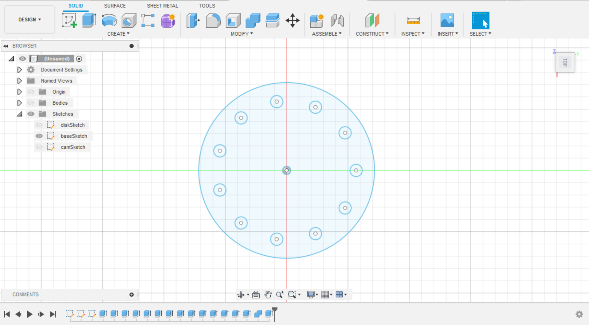
I’m not going to discuss the UI implementation, as the Fusion 360 API makes that pretty clear-cut, and interestingly enough some of the most challenging parts of this project were things I thought would be easy. As a result, I’m going to discuss purely the method that draws the 3 bodies. Below is an example of the UI and its default values in Fusion, and the document it creates:
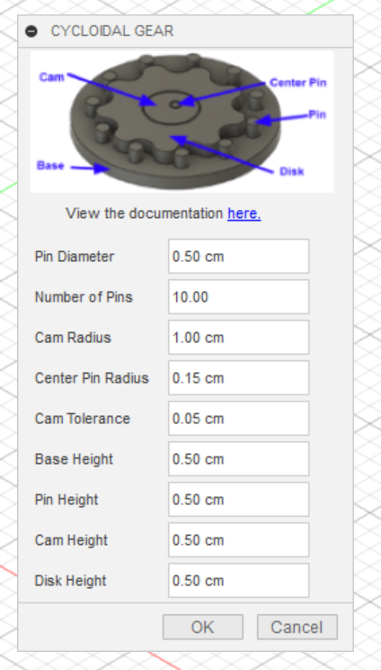
For a full description of using the script and the input parameters, click here. As you can see, this script takes in 9 input parameters. These are the necessary ingredients for this script, and as a result the function signature got a bit crowded. I’ll be the first to admit that this isn’t the best function I’ve ever written, and something that will have to be refactored. With that in mind, below is the beginning of the function that draws the 3 sketches in Fusion 360, and extrudes the corresponding bodies:
# generates the cycloidal disk, cam, and base plate with pins
def drawCycloidalBodies(combineFeatures, app, xyPlane, sketches, extrudes, pinD, numPins, shaftR, centerpinR, tolerance, baseHeight, pinHeight, camHeight, diskHeight):
    # further calculations
    rotorR = pinD * numPins * 2 / 3
    eccentricity = pinD * 0.5

    # create sketches and tools/collections
    diskSketch = sketches.add(xyPlane)
    diskSketch.name = 'diskSketch'
    baseSketch = sketches.add(xyPlane)
    baseSketch.name = 'baseSketch'
    camSketch = sketches.add(xyPlane)
    camSketch.name = 'camSketch'
    diskCircles = diskSketch.sketchCurves.sketchCircles
    baseCircles = baseSketch.sketchCurves.sketchCircles
    camCircles = camSketch.sketchCurves.sketchCircles
    points = adsk.core.ObjectCollection.create()
    bodyCollection = adsk.core.ObjectCollection.create()
As you can see, this features some additional input parameters, such as the components that will be used to make reference to the document in Fusion, as well as the items that will allow us to create sketches and extrude them to create our bodies. Next, some further calculations are made, which will be touched upon in the next section that details the mathematical calculations. After that, we create the main objects we need to construct our sketches and bodies. This includes creating a sketch per each body, naming it accordingly, and making additional objects and collections where necessary, such as in the case of the objects that allow us to sketch circles.
Next, we have the code that draws the sketch for the cycloidal disk:
# create the sketch for the cycloidal disk
px = 0
py = 0
pz = 0
for i in range(361):
currentRad = i * math.pi / 180.0
# parametric equations to create a spline along the outer edge
px = (rotorR * math.cos(currentRad)) - (pinD * math.cos((currentRad) + math.atan(math.sin((1 - numPins) * (currentRad)) /
((rotorR / eccentricity * numPins) - math.cos((1 - numPins) * (currentRad)))))) -
(eccentricity * math.cos(numPins * (currentRad)))
py = (-rotorR * math.sin((currentRad))) + (pinD * math.sin((currentRad) + math.atan(math.sin((1 - numPins) * (currentRad)) /
((rotorR / eccentricity * numPins) - math.cos((1 - numPins) * (currentRad)))))) +
(eccentricity * math.sin(numPins * (currentRad)))
points.add(adsk.core.Point3D.create(px, py, pz))
spline = diskSketch.sketchCurves.sketchFittedSplines.add(points)
curves = diskSketch.findConnectedCurves(diskSketch.sketchCurves.sketchFittedSplines.add(points))
dirPoint = adsk.core.Point3D.create(0, 0, 0)
offsetCurves = diskSketch.offset(curves, dirPoint, pinD)
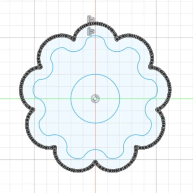
shaftHole = diskCircles.addByCenterRadius(adsk.core.Point3D.create(0, 0, 0), shaftR)This portion of the script begins by defining some coordinates that will be used when plotting the spline that makes up the outer profile of the cycloidal disk. Then, using a set of parametric equations that are detailed in the next section, these points are added to a list that will make up the drawn spline. This loop repeats 361 times such that the spline creates a closed curve. After the points have been added to the list, they are drawn as a spline in the sketch plane. From there, the curve is offset to form the actual profile of the cycloidal disk. Finally, the shaft hole is made. The entire sketch is generated by this code snippet is shown below:
disk sketch
The outer curve is generated by the loop that plots several points, while the inner curve is generated by the outer curve’s offset.
# extrude the disk
prof = diskSketch.profiles.item(2)
distance = adsk.core.ValueInput.createByReal(diskHeight)
diskExtrude = extrudes.addSimple(prof, distance,
adsk.fusion.FeatureOperations.NewBodyFeatureOperation)
disk = diskExtrude.bodies.item(0)
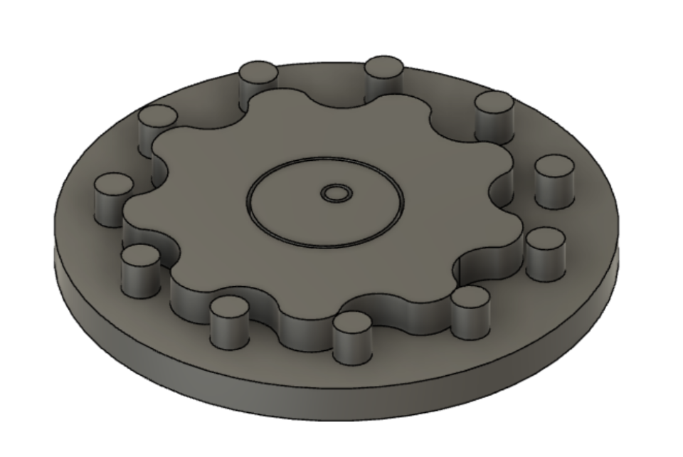
disk.name = "cycloidal disk"Finally, all that is left is to extrude the desired profile. The code to the right accomplishes this task. Note that within the profiles for this sketch, items such as the innermost circle as well as the portion in-between the outer curve and offset curve are valid selections. Due to this, we select the item at index 2 as the profile we wish to extrude, which is then extruded to the height specified by the user. The resulting body is then appropriately named, and is shown below:

Next, we are tasked with creating the base. The code for entire code for creating the base sketch and then extruding its components is shown below:
# create the sketch for the base
    baseCircle = baseCircles.addByCenterRadius(adsk.core.Point3D.create(0, 0, 0),
    app.measureManager.measureMinimumDistance(curves.item(0), dirPoint).value + pinD + 0.5)

    # extrude the base
    prof = baseSketch.profiles.item(0)
    distance = adsk.core.ValueInput.createByReal(-baseHeight)
    baseExtrude = extrudes.addSimple(prof, distance, adsk.fusion.FeatureOperations.NewBodyFeatureOperation)
    bodyCollection.add(baseExtrude.bodies.item(0))

    # create the sketch for the center pin
    centerPin = baseCircles.addByCenterRadius(adsk.core.Point3D.create(0, 0, 0), centerpinR)

    # extrude the center pin
    prof = baseSketch.profiles.item(1)
    distance = adsk.core.ValueInput.createByReal(pinHeight)
    baseExtrude2 = extrudes.addSimple(prof, distance, adsk.fusion.FeatureOperations.NewBodyFeatureOperation)
    base2 = baseExtrude2.bodies.item(0)

    # create the sketches for the outer pins
    degreeInc = (360.0 / (numPins+1)) * (math.pi / 180.0)
    x = 0
    y = app.measureManager.measureMinimumDistance(curves.item(0), dirPoint).value + pinD*0.5
    z = 0
    count = 2
    for i in range(numPins+1):
        baseCircles.addByCenterRadius(adsk.core.Point3D.create(x, y, z), pinD * 0.5)
        newy = x*math.sin(degreeInc) + y*math.cos(degreeInc)
        newx = x *math.cos(degreeInc) - y*math.sin(degreeInc)
        x = newx
        y = newy
        prof = baseSketch.profiles.item(count)
        distance = adsk.core.ValueInput.createByReal(pinHeight)
        baseExtrudes = extrudes.addSimple(prof, distance, adsk.fusion.FeatureOperations.NewBodyFeatureOperation)
        count  = count + 1
        bodyCollection.add(baseExtrudes.bodies.item(0))

    # combine the base components into one body
    combineFeatureInput = combineFeatures.createInput(base2, bodyCollection)
    combineFeatureInput.operation = 0
    combineFeatureInput.isKeepToolBodies = False
    combineFeatureInput.isNewComponent = False
    returnValue = combineFeatures.add(combineFeatureInput)
    returnValue.timelineObject.rollTo(True)
    base = returnValue.targetBody
    base.name = "base"
    returnValue.timelineObject.rollTo(False)
As you might have noticed, the structure of this code snippet differs from the last one. Within this sketch, we draw individual components, such as the base, extrude it, and then move on to the next parts. As you can see, we first draw the base and center pin, and extrude them. From there, we add them to a collection of bodies that will be unified later. Then, a for-loop draws the outer pins, rotating around the first circle that was drawn, and extruding them individually and adding them to the collections. Finally, we must unify all of these extrusions and their resultant bodies into a single body. In an interesting way, this ended up being the hardest thing for me to figure out. The main idea is that after collecting the bodies you wish to unify, you make a combineFeatureInput, which returns a new body that is the unification of all the input bodies. Then, this body is named appropriately, and the timeline is adjusted to allow this body to be shown. Below are the resultant sketch and body from this code snippet; in the timeline of the project you can see each individual extrusion, and then the combine operation, which I thought was interesting.

Finally, we have the code to make and extrude the sketch for the cam:
# create the sketch for the cam, allowing for tolerances
    shaftHole = camCircles.addByCenterRadius(adsk.core.Point3D.create(0, 0, 0), shaftR - (tolerance))
    # pinD*0.5
    offsetPin = camCircles.addByCenterRadius(adsk.core.Point3D.create(0, pinD * 2 / 3, 0), centerpinR + tolerance)

    # extrude the cam
    prof = camSketch.profiles.item(0)
    distance = adsk.core.ValueInput.createByReal(camHeight)
    camExtrude = extrudes.addSimple(prof, distance, adsk.fusion.FeatureOperations.NewBodyFeatureOperation)
    cam = camExtrude.bodies.item(0)
    cam.name = "cam"
As you can see, in comparison to the geometry created above, the cam was a welcome change of pace. All we had to do was draw the two circles; the outer profile and eccentric shaft hole, with their appropriate tolerances. Additionally, since this sketch was less complex, and resulted in a single body, this code remained very simple. The resulting sketch and body are shown below:


And that concludes the script! From a coding standpoint; it was pretty simple. Drawing shapes and extruding them was easy to figure out. However, the math around the gear was more of a challenge, which I touch upon in the next section.
mathematics of a cycloidal gear
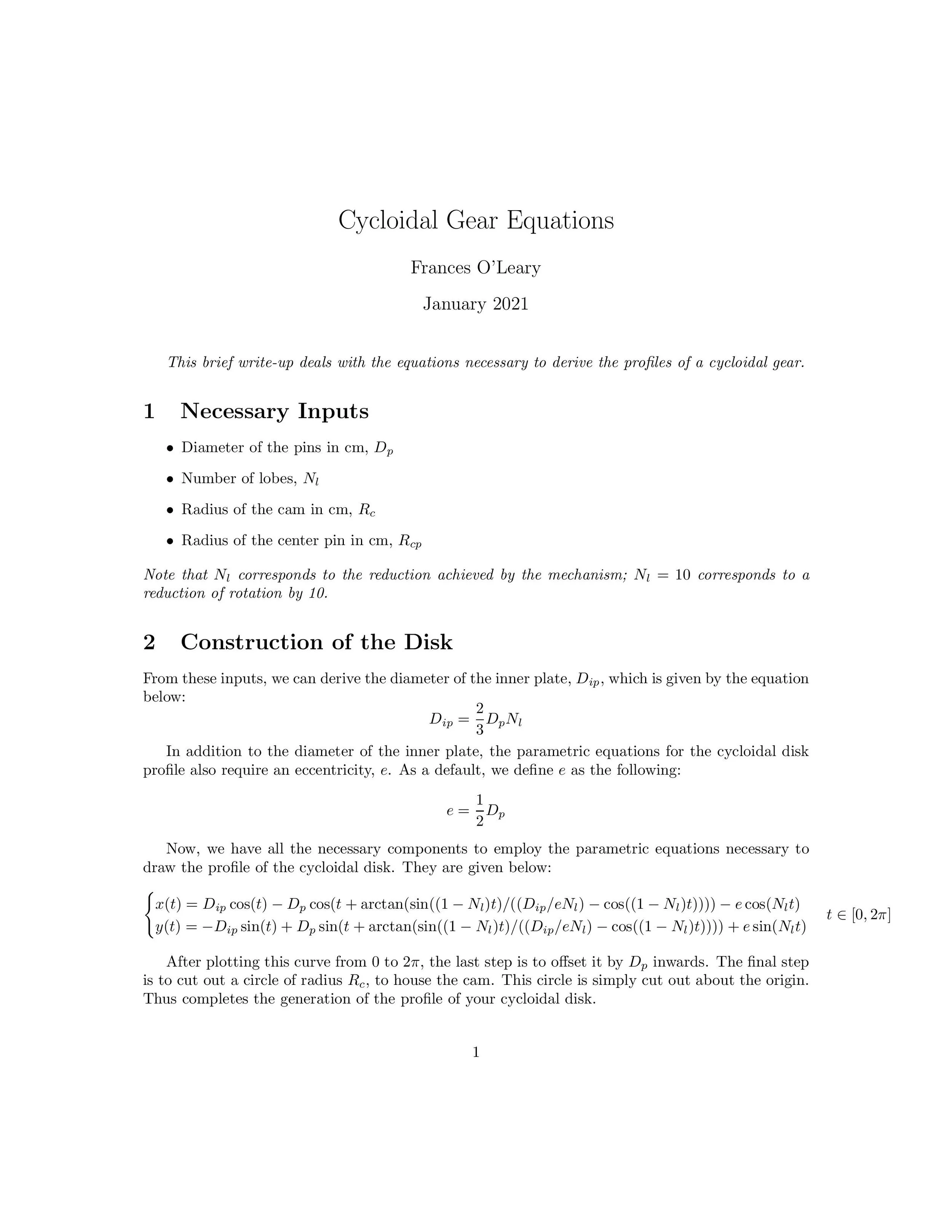
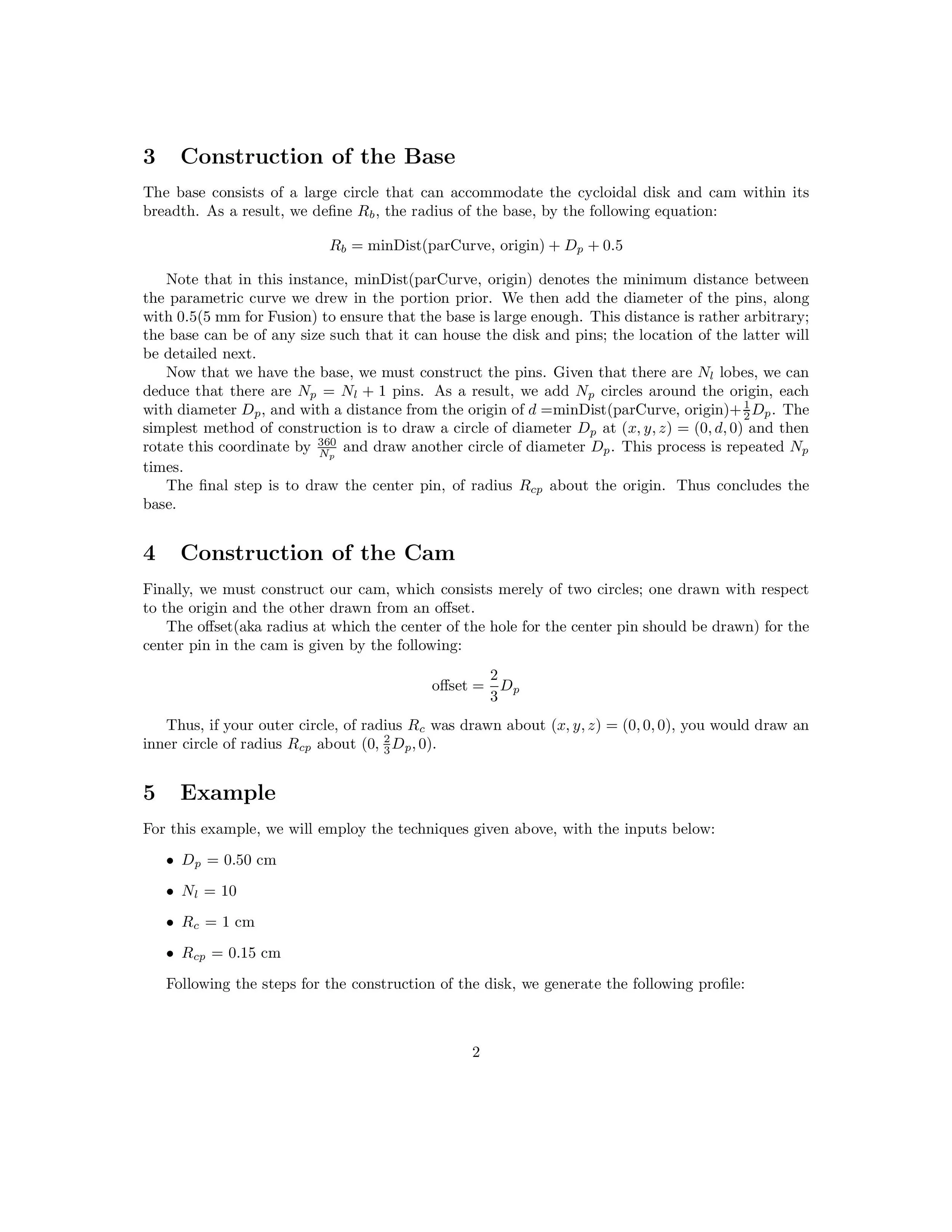
When I first started this project, I took to YouTube and found the video to the right. It’s a really wonderful video about manually modeling a cycloidal gear in Fusion 360, but with a fatal flaw that doesn’t translate well to coding: they manually draw the epicycloidal curves, instead of drawing them parametrically. So, before I found out you could draw the profile of the cycloidal gear with parametric curves, I manually rotated a circle around another using various rotation matrices and dropped points to create the outer spline. While not a great approach, it was certainly a nice refresher on geometry. However, while I ended up deviating from the approach detailed in this video, I still used it as a reference for various other measurements, such as the offset of the center pin hole in the cam. Besides this video, I used this excellent PDF to find a parametric solution to the problem. Both of these sources were instrumental to this project and were how I generated the following relations(the full PDF can be found here):


next steps
In terms of next steps, you can view current things I have in mind for this script on the readme.md of the project. As of right now, I mainly just want to make it robust and have it recognize user inputs that will cause it to crash or produce unwanted results, such as if an inputted cam radius is larger than the resultant cycloidal disk radius and results in odd extrusion. Besides that, in the future I would like to actually employ a cycloidal drive in a robot, and make a script that generates a cycloidal drive with two opposing cycloidal disks that is more than just the proof of concept gear that is rendered here. Additionally, having the script generate the bodies as components with joints ready for animation would also be very neat!
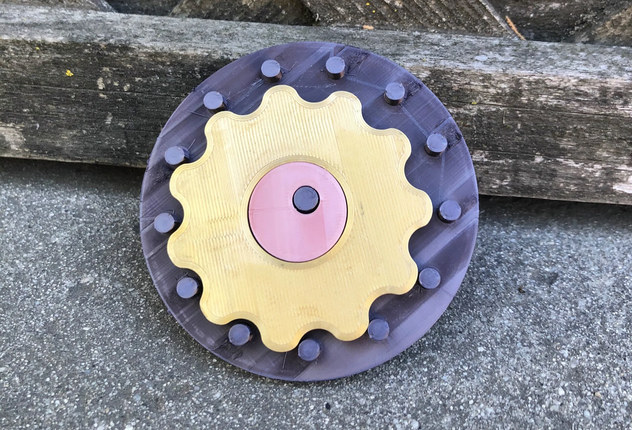
Below is the final set up, and a video to go along with it. The streaks along the build plate are due to me forgetting I had ironing enabled in Cura. . . a by-product of a project I’ll detail soon! I’ve been having an interesting time animating the components in Fusion 360, but if I ever get that I’ll make sure to post that here too!